Liquid Damage Repair
Corrosion is the unfortunate byproduct of the union between a ferrous alloy, ionic solute, electricity and air that results from bubble tea leaking inside the backpack of a student’s laptop as their MacBook silently dies. Liquid damage can result in a laptop that doesn’t power on, and data that is trapped in the logic board on newer devices that do not have removable storage drives.
Fortunately, Vancouver Mac Service Centre is equipped with state of the art micro-soldering and rework equipment, proprietary circuit diagrams and the experience of 100s of logic board repairs to reverse this damage and restore MacBooks to their original condition.
M1 MacBook Pro Logic Board Repair
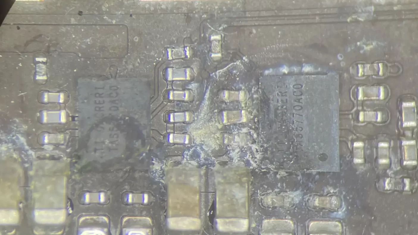
Here, the logic board repair for this liquid damaged A2338 M1 MacBook Pro is outlined. Firstly, a visual inspection is performed using a stereo microscope to identify any visual damage to the components.


Due to the liquid damage, significant corrosion has affected the portions of the logic board responsible for generation for the 3 and 5 volt accessory rails, display backlight output rail and speaker amplifiers. Looking more closely, some damaged components could be found:


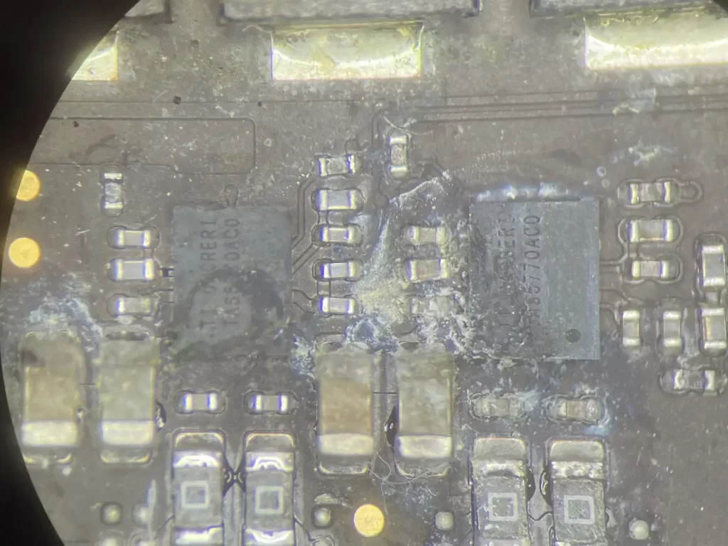
With the help of a hot air rework station, the damaged resistors were promptly erased, and audio amplifiers lifted off the board:


However, replacing these components did not restore the logic board; and it is still only drawing 5 volts through its USB-C power source. This indicates that the USB-C port controller is not able to negotiate the power delivery contract with the USB-C charger to boost the delivered voltage to 20V to allow for powering on. The first place to look is for the predicate power rails.

On Intel platform logic boards, these power rails are designated by a “_G3H” suffix (Intel ACPI power state G3 is ‘Mechanical Off’), meaning they should be powered on at all times, even when fully shutdown. The nomenclature has been changed to “_AON”, presumably short for “always-on”. Checking the voltage for the primary power rail PPBUS_AON, 12.3V is observed, which is the expected value.
Next in line is PP3V8_AON, which powers the main PMU (power management unit) which distributes low-voltage high-amperage rails for the M1 processor. PP3V8_AON measures 0V, and a diode mode measurement of 0.13V, which are both abnormal readings. Without PP3V8_AON, the USB-C port controllers cannot negotiate 20V from the charger.
First, the enable signal for the PP3V8_AON buck converter IC (U5700) is checked. 3.3 volts is measured, which is the expected value. This indicates that the power rail is being instructed by the controller for PPBUS_AON to power on. The presence of the signal makes U5700 a suspect.
U5700 is inspected, and there are no other abnormal diode mode readings associated with it. Furthermore, it is generating its internal LDO (low-dropout) PP5V_AON, indicating that the chip is at least partially working. Attention is shifted downstream to the 3 phase boost converter that the chip is controlling, and its MOSFETs that perform the switching.
Diode mode readings are normal for all pins of each of the three MOSFETs, and passive components pass testing as well. At this point, U5700 is replaced to eliminate it as a potential cause for the issue. The charger is connected, and 20V is now streaming through the USB-C port! All power rails are now coming up, indicating a successful liquid damage repair.


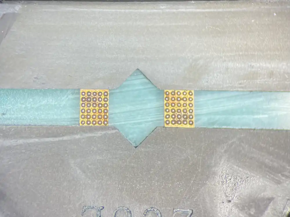
Before the laptop is closed up and tested, the audio circuit has not been fully repaired yet and that must be finished up. Both audio amplifiers that were previously removed are stripped of the old solder then cleaned. These chips are BGA (ball grid array) chips, and so solder paste is used to create the microscopic balls that connect them to the circuit board. Then, the chips are soldered precisely back on to their original landings.